Rapid Object-oriented Analysis and Design
Context Mapper offers transformation tools that support users in creating object-oriented domain models (that leverage DDD patterns) from use cases or user stories (functional requirements) rapidly.
Modeling Process
The transformations support the following process:
- Step 1: Capture User Requirements as Use Cases and/or User Stories in the Context Mapper DSL (CML)
- This is a manual step.
- The syntax documentation can be found here.
- Step 2: Derive DDD Subdomains from the functional requirements
- We offer a transformation that automates this step.
- Of course you can adjust and improve the generated Subdomains manually.
- Step 3: Derive DDD Bounded Contexts (type FEATURE) from the Subdomains
- Context Mapper offers a transformation that executes this step.
- The generated Bounded Contexts represent features or applications. Have a look at our Bounded Context types to understand how we distinguish between features, applications, systems, and teams.
- The generated model elements contain
TODOsuggestions for further elaboration.
- Step 4: Derive SYSTEMs from the FEATUREs (optionally, if you want to model
the application from a more physical perspective)
- We offer transformations to model the FEATURE or APPLICATION Bounded Contexts in terms SYSTEMS in order to model the physical (deployment) perspective.
- Find more about the different types of Bounded Contexts here.
- The generated Bounded Context model the different systems or subsystems of one application (frontend and backend, and/or other subsystems).
- We offer transformations to model the FEATURE or APPLICATION Bounded Contexts in terms SYSTEMS in order to model the physical (deployment) perspective.
In the following we illustrate the process with an example (fictitious insurance example).
Step 1: Capture User Requirements
The Context Mapper DSL (CML) language allows you to model requirements in the form of user stories or rather brief use cases. These two concepts differ in their context, goals and templates widely; however, CML supports the same role-feature-reason structure for both of them at present. The following example illustrates the syntax for both notations:
UserStory US1_Example {
  As an "Insurance Employee" I want to "create" a "Customer" so that "I am able to manage customer data ..."
}

UseCase UC1_Example {
  actor = "Insurance Employee"
  interactions = "create" a "Customer"
  benefit = "I am able to manage customer data ..."
}
It is also possible to specify multiple features or interactions in one use case or user story:
UserStory US1_Example {
  As an "Insurance Employee"
    I want to "create" a "Customer"
    I want to "update" a "Customer"
    I want to "offer" a "Contract"
  so that "I am able to manage the customers data and offer them insurance contracts."
}

UseCase UC1_Example {
  actor = "Insurance Employee"
  interactions = "create" a "Customer", "update" a "Customer", "offer" a "Contract"
  benefit = "I am able to manage the customers data and offer them insurance contracts."
}
Step 2: Derive Subdomains (with Services and Entities)
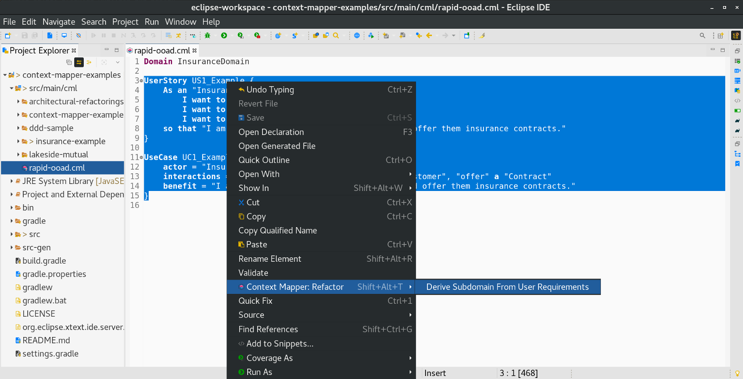
Once you have specified your user stories and/or use cases, you can select them in the CML editor and derive Subdomains that contain tentative Entities and Services automatically. The transformation can be found in Context Mappers refactoring context menu:
A dialog then allows you to choose your domain (declare the domain first) and define the name of the subdomain that shall be created:
Note: It is also possible to select an already existing Subdomain. In this case the transformation will only re-create the elements inside the Subdomain that do not exist already. You can update a Subdomain with new user stories or use cases iteratively without loosing your manual changes this way.

If we use the example user story above and apply the transformation, we get the following Subdomain:
Domain InsuranceDomain {
  Subdomain CustomerDomain {
    domainVisionStatement "Aims at promoting the following benefit for a Insurance Employee: I am able to manage the customers data and offer them insurance contracts."
    Entity Customer
    Entity Contract
    Service US1_ExampleService {
      createCustomer;
      updateCustomer;
      offerContract;
    }
  }
}
The resulting Subdomains contain entities that are derived from the objects that the use case/user story works with as as well as services that represent the use case/user story; the interactions are transformed into draft operations.
After the generation of the Subdomain one can detail and improve it manually; in order not to loose any manual additions when the transformation is executed multiple times, it makes sense to rename the element. A “rename element” refactoring can be used for this.
Step 3: Derive Bounded Contexts
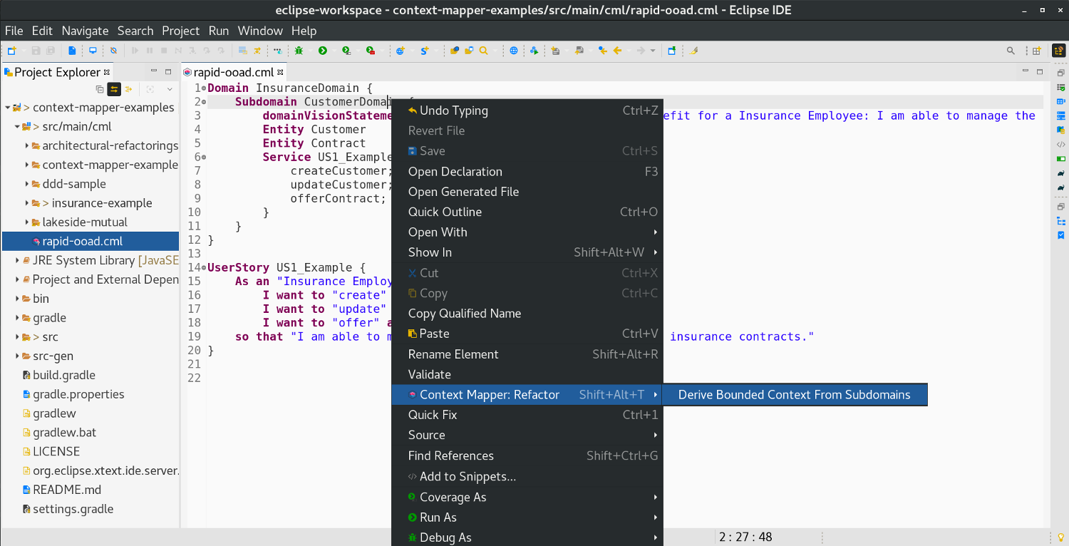
Another transformation allows you to transition from analysis to design and generate Bounded Context definitions from existing Subdomains in CML. You can simple select one or multiple Subdomains and select the Derive Bounded Context from Subdomains option that can be found in the refactoring context menu:
Note that the transformation always creates one Bounded Context for all selected Subdomains.
Using the example Subdomain above, the transformation generates the following Bounded Context:
BoundedContext NewContextFromSubdomains implements CustomerDomain {
  domainVisionStatement "This Bounded Context realizes the following subdomains: CustomerDomain"
  /* This Aggregate contains the entities and services of the 'CustomerDomain' subdomain.
   * TODO: You can now refactor the Aggregate, for example by using the 'Split Aggregate by Entities' architectural refactoring.
   * TODO: Add attributes and operations to the entities.
   * TODO: Add operations to the services.
   * Find examples and further instructions on our website: https://contextmapper.org/docs/rapid-ooad/ */
  Aggregate CustomerDomainAggregate {
    Service US1_ExampleService {
      CreateCustomerOutput createCustomer (CreateCustomerInput input);
      UpdateCustomerOutput updateCustomer (UpdateCustomerInput input);
      OfferContractOutput offerContract (OfferContractInput input);
    }
    Entity Customer {
      CustomerID customerId
    }
    Entity Contract {
      ContractID contractId
    }
  }
}
The generated Bounded Context implements the previously selected Subdomains and initially contains an Aggregate per Subdomain that includes all entities and services of those Subdomains. The entities are enriched with identify attributes, and the services operations receive a generic return type and parameter.
As the TODO comments indicate, a user can now refactor the resulting Aggregate (for example by using Split Aggregate by Entities), and add further details such as attributes (entities) and operations (entities/services).
Step 4: Derive Systems
The Bounded Contexts generated in the step three above represent FEATUREs and/or APPLICATIONs (find more about the different types of Bounded Context here). If you want to model such an application or feature context from a more physical- or deployment perspective, you can now derive Bounded Contexts of the type SYSTEM from them.
Derive Frontend and Backend Systems
We renamed the Bounded Context NewContextFromSubdomains from above to CustomerManagement now. As already mentioned, it represents a feature or application. On such Bounded Context we can now apply the Derive Frontend and Backend Systems transformation to model the systems/subsystems of the application:

A dialog lets you choose the names of your frontend and backend application:
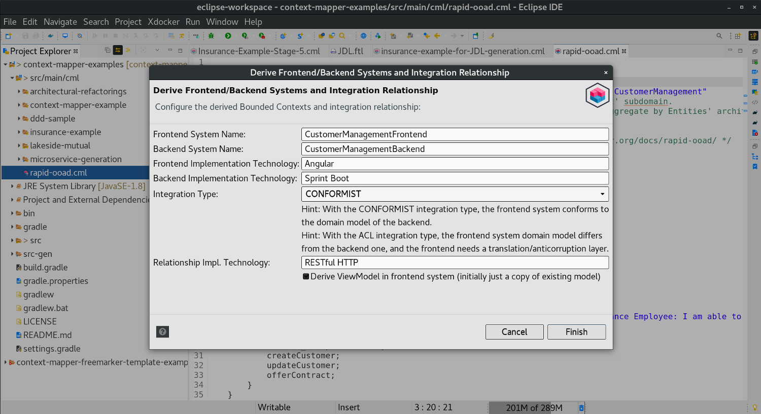
You can further configure the implementation technologies of the contexts. In addition, you can define how the backend and frontend context shall integrate:
- CONFORMIST: In this case the frontend domain model conforms to the backend model.
- ACL: If the domain model of the frontend context differs from the backend, the frontend context needs a transformation or anticorruption layer.
Applying the transformation as shown above generates the following Bounded Contexts and Context Map relationship:
ContextMap {
  contains CustomerManagementFrontend
  contains CustomerManagementBackend

  CustomerManagementBackend [PL] -> [CF] CustomerManagementFrontend {
    implementationTechnology "RESTful HTTP"
    exposedAggregates CustomerManagementAggregateBackend
  }
}

BoundedContext CustomerManagementBackend implements CustomerManagement {
  domainVisionStatement "This Bounded Context realizes the following subdomains: CustomerManagement"
  type SYSTEM
  implementationTechnology "Sprint Boot"
  Aggregate CustomerManagementAggregateBackend {
    Service US1_ExampleService {
      CreateCustomerOutput createCustomer (CreateCustomerInput input);
      UpdateCustomerOutput updateCustomer (UpdateCustomerInput input);
      OfferContractOutput offerContract (OfferContractInput input);
    }
    Entity CustomerBackend {
      CustomerID customerId
    }
    Entity ContractBackend {
      ContractID contractId
    }
  }
}

BoundedContext CustomerManagementFrontend implements CustomerManagement {
  domainVisionStatement "This Bounded Context realizes the following subdomains: CustomerManagement"
  type SYSTEM
  implementationTechnology "Angular"
  Aggregate CustomerManagementAggregateViewModel {
    Service US1_ExampleService {
      CreateCustomerOutput createCustomer (CreateCustomerInput input);
      UpdateCustomerOutput updateCustomer (UpdateCustomerInput input);
      OfferContractOutput offerContract (OfferContractInput input);
    }
    Entity CustomerViewModel {
      CustomerID customerId
    }
    Entity ContractViewModel {
      ContractID contractId
    }
  }
}
Now you already have an Upstream-Downstream relationship that exposes an Aggregate, which means you can generate a service contract with our MDSL (Micro-)Service Contracts Generator. Of course you can use all the other generators as well.
Split System Context Into Subsystems
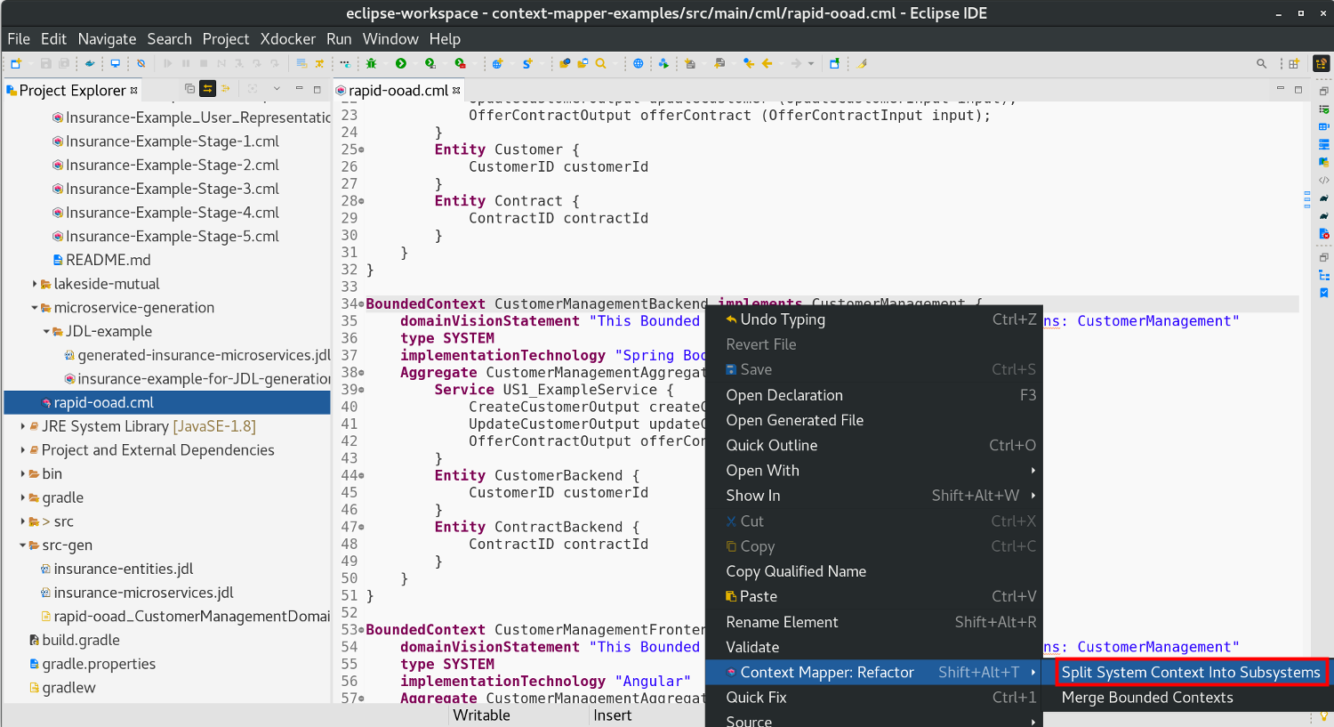
Having derived a frontend and backend system, you may want to split the systems into multiple subsytems. For example: your backend maybe consists of a domain logic and a database subsystem (or tier). We provide another model transformation to split a system into two subsystems for such a case:
Similar to the last transformation you can configure how the subsystems are named and how they shall integrate (see CONFORMIST vs. ACL above):
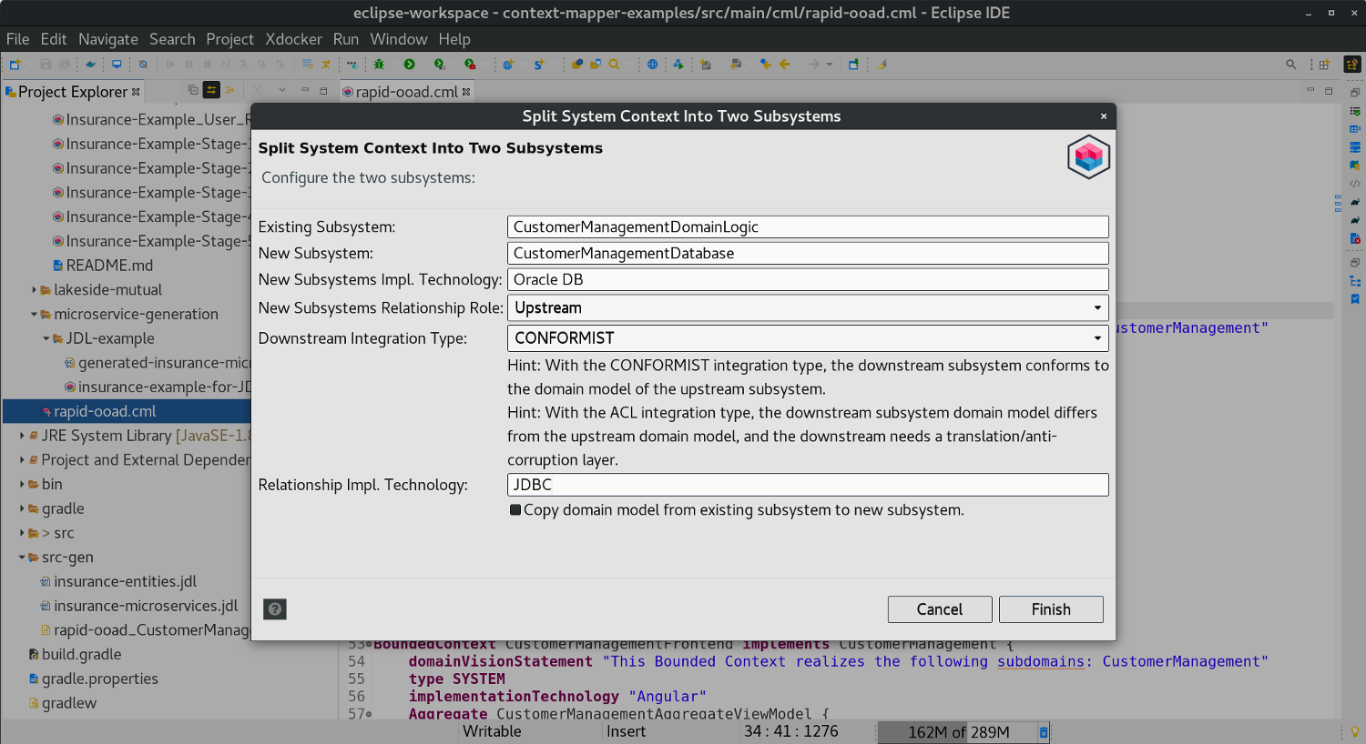
Note: This transformation does not create two new Bounded Contexts. It uses the existing context for the first subsystem and creates one new Bounded Context for the second subsystem.
The transformation leads to the following result (with the configuration as shown above):
ContextMap {
  contains CustomerManagementFrontend
  contains CustomerManagementDomainLogic
  contains CustomerManagementDatabase

  CustomerManagementDomainLogic [PL] -> [CF] CustomerManagementFrontend {
    implementationTechnology "RESTful HTTP"
    exposedAggregates CustomerManagementAggregateBackend
  }

  CustomerManagementDatabase [PL] -> [CF] CustomerManagementDomainLogic {
    implementationTechnology "JDBC"
  }
}

BoundedContext CustomerManagementFrontend implements CustomerManagement {
  domainVisionStatement "This Bounded Context realizes the following subdomains: CustomerManagement"
  type SYSTEM
  implementationTechnology "Angular"
  Aggregate CustomerManagementAggregateViewModel {
    Service US1_ExampleService {
      CreateCustomerOutput createCustomer (CreateCustomerInput input);
      UpdateCustomerOutput updateCustomer (UpdateCustomerInput input);
      OfferContractOutput offerContract (OfferContractInput input);
    }
    Entity CustomerViewModel {
      CustomerID customerId
    }
    Entity ContractViewModel {
      ContractID contractId
    }
  }
}

BoundedContext CustomerManagementDomainLogic implements CustomerManagement {
  domainVisionStatement "This Bounded Context realizes the following subdomains: CustomerManagement"
  type SYSTEM
  implementationTechnology "Sprint Boot"
  Aggregate CustomerManagementAggregateBackend {
    Service US1_ExampleService {
      CreateCustomerOutput createCustomer (CreateCustomerInput input);
      UpdateCustomerOutput updateCustomer (UpdateCustomerInput input);
      OfferContractOutput offerContract (OfferContractInput input);
    }
    Entity CustomerBackend {
      CustomerID customerId
    }
    Entity ContractBackend {
      ContractID contractId
    }
  }
}

BoundedContext CustomerManagementDatabase {
  type SYSTEM
  implementationTechnology "JDBC"
}
Note: It is also possible to copy the domain model into the second subsystem (was not selected for the CustomerManagementDatabase context above) with the corresponding checkbox on the dialog.
You can model application architectures with more than two subsystems by applying this transformation multiple times.
What’s Next?
Once you derived your initial Bounded Contexts, you can:
- Add more details to the domain models (attributes, operations, services, repositories, etc.)
- Refine and refactor them by using our Architectural Refactorings.
- Define a Context Map that specifies the relationships between your Bounded Contexts.
- Generate output and other representations of you CML model:
- Graphical Context Map
- PlantUML diagrams
- MDSL (micro-)service contracts
- Generic output with Freemarker templates
- Use our JHipster JDL generator template to generate microservices code from your Context Map.
Related Links
- The Context Mapper OOAD transformations were presented at ICWE 2020 by Olaf Zimmermann: Find the slides and the demo here.
Frequently Asked Questions (FAQs)
- Whats the difference between the transformations described above and the Architectural Refactorings (ARs)?
- Some of the model transformations described here, such as Split System Context Into Two Subsystems, may seem similar to some of our ARs (Split Bounded Context by …). However, there are different ideas behind the concepts.
- The OOAD transformations above are designed to evolve a CML model from functional requirements rapidly. The transformations typically generate new elements into your model.
- The Architectural Refactorings (ARs) on the other hand are designed to change/improve an existing model and architecture. They typically do not add new elements to the model, but restucture the existing CML model.