Application and Process Layer
The original “blue book” (by Evans) as well as the “red book” (by Vernon) talk about domain and application layers. Although Context Mapper is focused on strategic DDD and domain models (domain layer) inside Bounded Contexts, we support modeling services, commands, and events in an application layer. With the application layer concept in CML users have the possibility to declare which services and/or commands can be called/triggered from outside a Bounded Context and which events are published to the outside.
In addition to that, the application layer offers a basic syntax to model processes or event/command flows. This can, for example, be helpful to bring events and commands (maybe outcome of an Event Storming) into a timeline and explicitly state which event are emitted by which commands (or service operations) and which commands are triggered by events.
The application layer also provides an alternative way to model processes without relying on event/command syntax. This is achieved by defining a coordination between service operations.
Application Services and Commands
DDD practitioners and experts typically distinguish between domain services and application services. Therefore, CML offers the possibility to use the service construct both inside Aggregates (domain service) and inside the application layer (application service). Note that the grammar/syntax for application services is exactly the same as for the services inside the Aggregates.
The following example illustrates how to model an application layer in a Bounded Context and add application services:
BoundedContext ClaimsManagement {
  Application {
    Service ClaimsApplicationService {
      void submitClaim(@Claim claim);
      void checkInsurance(@Claim claim);
      void acceptClaim(@Claim claim);
      void rejectClaim(@Claim claim);
    }
  }

  Aggregate Claims {
    Entity Claim {
      aggregateRoot
      long claimId
      CustomerId customer
      String description
      Blob requestDocument
      boolean isComplete
      boolean isAssessed
      - ClaimState claimState
    }
    enum ClaimState {
      aggregateLifecycle
      OPEN, REJECTED, ACCEPTED
    }

    abstract DomainEvent ClaimEvent {
      long claimId
      Date timestamp
    }
    DomainEvent ClaimSubmitted extends ClaimEvent
    DomainEvent ClaimAccepted extends ClaimEvent
    DomainEvent ClaimRejected extends ClaimEvent
  }
}
Optionally, it is possible to name the application layer:
Application ClaimsApplicationLayer {
  Service ClaimsApplicationService {
    void submitClaim(@Claim claim);
    void checkInsurance(@Claim claim);
    void acceptClaim(@Claim claim);
    void rejectClaim(@Claim claim);
  }
}
As documented on the Aggregate page, it is also possible to specify state transitions made by operations. Please consult the Aggregate documentation for the syntax of state transitions. The same syntax is available for the operations of application services:
Application {
  Service ClaimsApplicationService {
    void submitClaim(@Claim claim) : write [ -> OPEN];
    void checkInsurance(@Claim claim);
    void acceptClaim(@Claim claim) : write [ OPEN -> ACCEPTED ];
    void rejectClaim(@Claim claim) : write [ OPEN -> REJECTED ];
  }
}
Hint: If you model processes/flows (see documentation of syntax below) you may want to declare the state transitions in the flow steps instead of service operations.
As an alternative to “service operations” you can also create semantically equivalent commands and events in the application layer; maybe you work with Event Sourcing and/or CQRS, and these terms fit better.
The syntax for domain events and commands is documented on the tactic DDD reference page. The following example illustrates how you can use those concepts in the application layer as well:
Application {
  Command SubmitClaim {
    // attributes/body optional
  }
  Command AcceptClaim
  Command RejectClaim

  Event ClaimSubmitted {
    // attributes/body optional
  }
  Event ClaimAccepted
  Event ClaimRejected
}
Hint: Modeling commands that are triggered by users or external systems in the application layer may feel natural. Events, however, may be part of your domain model. Therefore you should decide consciously whether you want to model these events on the application layer or inside the corresponding domain layer Aggregate.
Processes and Event/Command Flows
In addition to application services and commands, the application layer offers language features to model event/command flows. Events typically occur in a certain order over time. For example in Event Stormings Events are typically ordered by the timeline from left to right. An example: (from our Event Storming tutorial)
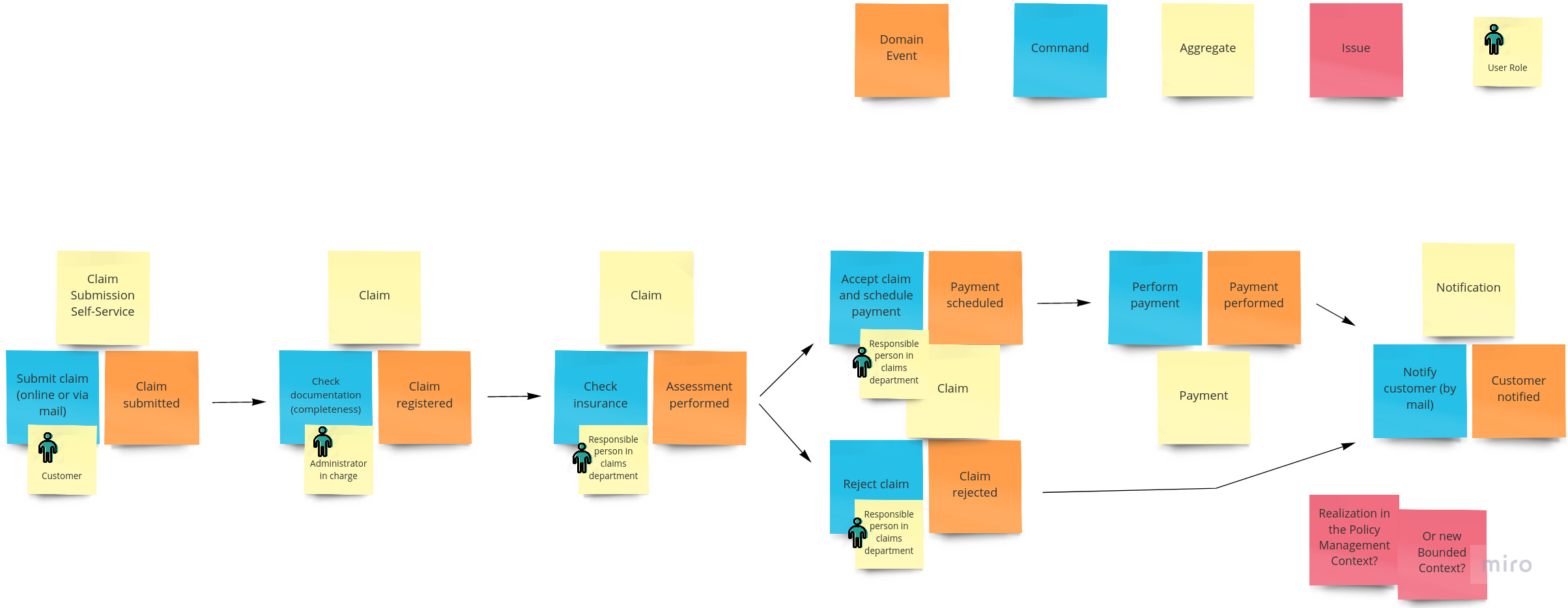
Our flow grammar supports Context Mapper users in modeling such event/command flows in CML. The following example models the event storming result illustrated above:
Application {

  /* we removed commands and events here to keep the sample shorter */

  Flow ClaimsFlow {
    command SubmitClaim emits event ClaimSubmitted
    event ClaimSubmitted triggers command CheckClaimDocumentation
    command CheckClaimDocumentation emits event ClaimRegistered
    event ClaimRegistered triggers command CheckInsurance
    command CheckInsurance emits event AssessmentPerformed

    event AssessmentPerformed triggers command AcceptClaim X RejectClaim
    command AcceptClaim delegates to Claims [OPEN -> ACCEPTED] emits event ClaimAccepted
    command RejectClaim delegates to Claims [OPEN -> REJECTED] emits event ClaimRejected

    event ClaimAccepted triggers command SchedulePayment
    command SchedulePayment emits event PaymentPerformed
    event PaymentPerformed triggers command NofifyCustomer
    event ClaimRejected triggers command NofifyCustomer
    command NofifyCustomer delegates to Claims [ACCEPTED, REJECTED -> CUSTOMER_NOTIFIED] emits event CustomerNotified
  }
}
The example above works with commands. It is however possible to model the same flow with service operations:
Application {
  Service ClaimsApplicationService {
    void submitClaim(@Claim claim);
    void checkClaimDocumentation(@Claim claim);
    void checkInsurance(@Claim claim);
    void acceptClaim(@Claim claim);
    void rejectClaim(@Claim claim);
    void schedulePayment(@Claim claim);
    void nofifyCustomer(@Claim claim);
  }

  Flow ClaimsFlow {
    operation submitClaim emits event ClaimSubmitted
    event ClaimSubmitted triggers operation checkClaimDocumentation
    operation checkClaimDocumentation emits event ClaimRegistered
    event ClaimRegistered triggers operation checkInsurance
    operation checkInsurance emits event AssessmentPerformed

    event AssessmentPerformed triggers operation acceptClaim X rejectClaim
    operation acceptClaim delegates to Claims [OPEN -> ACCEPTED] emits event ClaimAccepted
    operation rejectClaim delegates to Claims [OPEN -> REJECTED] emits event ClaimRejected

    event ClaimAccepted triggers operation schedulePayment
    operation schedulePayment emits event PaymentPerformed
    event PaymentPerformed triggers operation nofifyCustomer
    event ClaimRejected triggers operation nofifyCustomer
    operation nofifyCustomer delegates to Claims[ACCEPTED, REJECTED -> CUSTOMER_NOTIFIED] emits event CustomerNotified
  }
}
In the following we explain the grammar in detail and step by step…
Flow Grammar
There are basically two types of flow steps that are supported by CML:
- Type 1: an event triggers an operation/command (command/operation invocation)
- Type 2: a command/operation emits an event (event production)
These types of steps are inspired by the Event Storming Cheat sheet of the DDD crew, the following illustration in particular:

Note: We do not support all of the concepts illustrated above! Especially policies and the “query model / information” sticky are not supported explicitly.
The picture above illustrates the two main step types mentioned above.
- Type 1: an event triggers (the DDD crew uses the term issues) a command (in CML without the policy in between)
- Type 2: a command (CML: or operation) invoked on an Aggregate emits (the DDD crew uses the term produces) an event
In the following we will see that we also support the Aggregate in Type 2; the actor that can trigger a command/operation.
The following example illustrates the basic syntax of the two step types:
Application {

  /* we removed commands and events here to keep the sample shorter */

  Flow ClaimsFlow {
    /* type 2: (event production) */
    command SubmitClaim emits event ClaimSubmitted

    /* type 2 alternative: (event production) */
    operation submitClaim emits event ClaimSubmitted

    /* type 1: (command invokation) */
    event ClaimSubmitted triggers command CheckClaimDocumentation

    /* type 1 alternative: (operation invokation) */
    event ClaimSubmitted triggers operation checkClaimDocumentation
  }
}
Emitting Events
A command or operation can emit multiple events. This is expressed with the + sign as follows:
command SubmitClaim emits event Event1 + Event2 + Event3 // and so on... (emit as many events as you want)

// alternative
operation submitClaim emits event Event1 + Event2
The example above illustrates that an operation emits multiple events events, which means, all events are emitted!
There are situations in which you want to express that one OR an other event is emitted. In this case, we distinguish between exclusive OR (XOR: only one of the listed events is emitted) and inclusive OR (multiple events can be thrown, but not necessarily all). For these two cases we use the symbols X and O, inspired by BPMN.
Exclusive variant:
command SubmitClaim emits event Event1 X Event2 X Event3

// alternative
operation submitClaim emits event Event1 X Event2
Inclusive variant:
command SubmitClaim emits event Event1 O Event2 O Event3

// alternative
operation submitClaim emits event Event1 O Event2
Symbol Summary:
The following table summarizes the three symbols that are supported here:
| Symbol | Meaning | Corresponding BPMN gateways (in German) |
|---|---|---|
| + | ALL listed events are emitted. | Parallel Gateway |
| X or x | ONLY ONE of the listed events is emitted. | Exclusive Gateway |
| O or o | ONE OR MULTIPLE, BUT NOT NECESSARILY ALL of the listed events are emitted. | Inclusive Gateway |
Note: It is not possible to mix the symbols inside a single flow step (we do not implement operator precedence).
Command/Operation triggered by multiple Events
On the other hand a command or operation may only be triggered if multiple events happen. This is modelled as follows:
event ClaimSubmitted + ContractChecked triggers command AssessClaim

// alternative
event ClaimSubmitted + ContractChecked triggers operation assessClaim
This example expresses that both events (ClaimSubmitted as well as ContractChecked) must have been emitted so that AssessClaim is triggered.
Note: At this point only the + symbol is supported.
Triggering Commands/Operations
Similar to the event productions explained above, it is possible that events trigger multiple commands/operations. This syntax works with the symbols +, X, and O again.
Parallel variant:
event ClaimSubmitted triggers command CheckClaim + CheckPolicy

// operation alternative:
event ClaimSubmitted triggers operation checkClaim + checkPolicy
This example expresses that all listed operations/commands are triggered (parallel).
Exclusive variant:
event ClaimSubmitted triggers command CheckClaim X CheckPolicy

// operation alternative:
event ClaimSubmitted triggers operation checkClaim X checkPolicy
This example means that only one of the commands/operations is triggered.
Inclusive variant:
event ClaimSubmitted triggers command CheckClaim O CheckPolicy

// operation alternative:
event ClaimSubmitted triggers operation checkClaim O checkPolicy
This example expresses that one or multiple but not necessarily all commands/operations are triggered.
Symbol summary:
The following table summarizes the meaning of the supported symbols in the command/operation invokation steps:
| Symbol | Meaning | Corresponding BPMN gateways |
|---|---|---|
| + | ALL listed commands/operations are triggered. | Parallel Gateway |
| X or x | ONLY ONE of the listed commands/operations is triggered. | Exclusive Gateway |
| O or o | ONE OR MULTIPLE, BUT NOT NECESSARILY ALL of the listed commands/operations are triggered. | Inclusive Gateway |
Commands/Operations delegating to Aggregates
Commands and operations are typically delegated to an Aggregate. This also corresponds to the illustration of the DDD crew depicted above.
In CML this means that you can optionally add the following reference to event production steps (Type 2 above):
command SubmitClaim delegates to Claims emits event Event1 X Event2 X Event3

// alternative
operation submitClaim delegates to Claims emits event Event1 X Event2
Note that this is a reference to an Aggregate that must actually exist in your Bounded Context. In the example above there must be an Aggregate called Claims in the same Bounded Context.
State Transitions
In case your flow step delegates to an Aggregate (contains part delegates to) as in the example above, it is possible to declare the state transition that is caused right here.
Note: State transition can be modelled on service and domain object operations as documented on the Aggregate doc page.
If you use flows you can add the state transitions to the flow steps instead of modeling them inside the Aggregate (operations). The state transitions can be added to the event production steps (type 2 above) as follows (optionally):
command SubmitClaim delegates to Claims [ -> SUBMITTED ] emits event Event1 X Event2 X Event3

// alternative
operation submitClaim delegates to Claims [ -> SUBMITTED ] emits event Event1 X Event2
For a complete documentation and examples for the state transition grammar we refer to the Aggregate page.
Actors
Commands or operations can be triggered by actors/users. In CML you can specify this (optionally) as follows:
command SubmitClaim [ initiated by "Customer" ] delegates to Claims [ -> SUBMITTED ] emits event Event1

// alternative
operation submitClaim [ initiated by "Customer" ] delegates to Claims [ -> SUBMITTED ] emits event Event1
Visualization with BPMN Sketch Miner
Once you modelled an application flow you can visualize it in the BPMN Sketch Miner. Use Context Mapper’s BPMN Sketch Miner generator to generate the Sketch Miner DSL output or directly open the visualization in the browser.
An example output: (visualization powered by BPMN Sketch Miner)
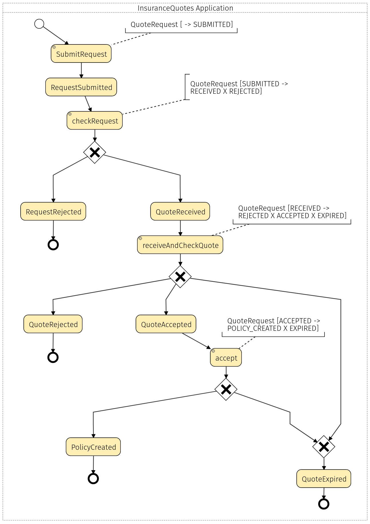
Note: This is a process we took (modeled) from the Lakeside Mutual project.
Coordination between Application Services
In case you want to model processes/workflows that span multiple Bounded Contexts without the use of event/command syntax, you can also do so by defining a coordination between application services. This language feature is based on the concept of Coordination from the “Software Architecture: The Hard Parts” book by Neal Ford and others. They define Coordination as a property of workflows, which can either be orchestrated (the workflow steps are coordinated by a central component) or choreographed (each step of the workflow shares coordination logic).
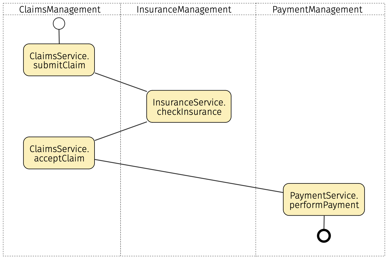
To model these workflows in Context Mapper, you use the coordination construct inside the application layer of a Bounded Context. The following example illustrates this using an adaptation of the same claims processing concept from before:
ContextMap {
  contains ClaimsManagement
  contains InsuranceManagement
  contains PaymentManagement

  ClaimsManagement <-> InsuranceManagement
  ClaimsManagement <-> PaymentManagement
}

BoundedContext ClaimsManagement {
  Application {
    Coordination SubmitValidClaimCoordination {
      ClaimsManagement::ClaimsApplicationService::submitClaim;
      InsuranceManagement::InsuranceApplicationService::checkInsurance;
      ClaimsManagement::ClaimsApplicationService::acceptClaim;
      PaymentManagement::PaymentApplicationService::performPayment;
    }

    Service ClaimsApplicationService {
      void submitClaim(@Claim claim);
      void acceptClaim(@Claim claim);
    }
  }
}

BoundedContext InsuranceManagement {
  Application {
    Service InsuranceApplicationService {
      void checkInsurance(@Claim claim);
    }
  }
}

BoundedContext PaymentManagement {
  Application {
    Service PaymentApplicationService {
      void performPayment(@Claim claim);
    }
  }
}
Note: The type of workflow coordination (orchestration or choreography) is not explicitly supported in the syntax, but can still be modeled by assuming that the Bounded Context where the coordination is defined serves as either the orchestrator, or the start of the choreography.
Coordination Grammar
In CML, coordinations are composed of coordination steps. Each coordination step represents a call to an application service operation, which can be defined inside the same Bounded Context or in an outer Bounded Context.
To correctly reference an application service operation, a coordination step is divided into three segments, separated by the :: symbol:
- The name of the Bounded Context where the operation is defined;
- The name of the application service where the operation is defined;
- And the name of the operation.
The following is an example of a coordination step:
// Bounded context name :: application service name :: service operation name
ClaimsManagement::ClaimsApplicationService::submitClaim;
Each of the three segments of a coordination step is also subject to certain syntax rules to maintain the integrity of the model. Respectively, these are:
- A coordination step can only reference outer Bounded Contexts that are upstream (by means of an upstream/downstream relationship or a symmetrical relationship in a Context Map definition);
- A coordination step can only reference services defined in the application layer of a Bounded Context (which means domain services defined inside aggregates are not applicable);
- A reference to a service operation in a coordination step should be unique within the service.
Coordination visualization in BPMN
Like flows, coordinations can also be visualized with BPMN Sketch Miner. The following example shows the output when using Context Mapper’s BPMN Sketch Miner generator on coordinations: